View Redirection on Mobile Cameras
Abstract
Mobile phones frequently include a camera that can capture snapshots and record videos. The camera is rigidly mounted on the mobile phone and cannot be swiveled, which sometimes forces the photographer to hold the camera in a inconvenient position. This note proposes placing an image-reflecting device such as a mirror in the field of view of the camera device. It enables the camera to record scenes that are not directly in front of it, allowing the photographer to hold the camera in a more convenient position. The tilt of the reflecting surface may be adjusted to suit the photographer. Furthermore, the reflecting device may be rotated around the axis of the camera’s field of view to allow the camera to record scenes that are oblique or to the side. This facilitates recording of both portrait and landscape mode pictures.
Background
Most modern mobile phones include a camera and a display. The image being recorded by the camera appears on the display on the front of the phone. The camera is usually rigidly mounted on the rear surface of the mobile phone. It can only record images along a line that is perpendicular to the rear surface of the phone; this is called the field of view. The photographer typically has to position the mobile phone so that the subject is in the field of view and that they can view the display, thus requiring them to hold the mobile phone in front of their face. Such a pose is often uncomfortable, looks awkward and makes it obvious to bystanders that the photographer is recording the scene.


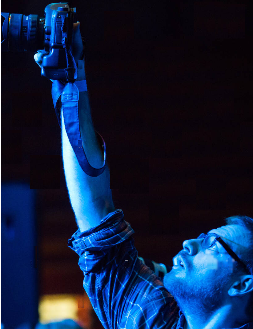
Furthermore, some scenes are very inconvenient to capture, for example, when the photographer wishes to take a shot over the heads of a crowd. The photographer in the picture above cannot view the screen to compose the shot correctly. Additionally, a photographer would have to place their face close to the floor to capture the view beneath a refrigerator.
The proposal aims to make recording images easier for photographers by placing a mirror in front of the camera lens. The mirror can be tilted and rotated to allow the camera to record alternative fields of view, not just the scene that is directly in front of it. This allows the camera to be held in a more convenient position while recording a scene.
The proposal addresses both still images and video content recorded by the camera. It also considers cameras that are stand-alone or mounted on devices other than mobile phones. The mirror can be mounted directly on the mobile phone or on a mobile phone case. The mirror may be convex, polarized or color-tinted for additional effects. It can include a lens. It can also be replaced by a different method of reflecting light, such as a refracting prism.
Major vendors like Google, Apple and Samsung will not be interested in building phones with cameras that swivel. The solution is to incorporate the mirror into cases that are customized for each phone. People who wish to have this capability can purchase a case for their specific device. For prototypes and low volume situations, cases can be made using 3D printers with low setup costs.
Detailed
Description
Most cameras today have a rigid physical connection between the camera lens, the camera body and the viewfinder display. This constraint requires the camera body to be positioned so that the lens is pointing directly at the subject to be photographed while the display is visible to the photographer. This often results in a odd and inconvenient camera orientation. The proposal aims to make recording images easier for photographers by positioning a mirror in front of the camera lens. The mirror would be mounted so that it can be tilted along different axes, thus allowing scenes at various directions to be recorded.
Figure 1 depicts a typical mobile phone camera held in portrait mode. The camera should be held in a direct line between the photographer’s face and the subject, which can be inconvenient. The inset shows the image on the mobile phone’s display.
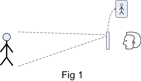
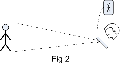
Figure 2 depicts the current proposal being used for a portrait mode recording. The mirror has been deployed allowing the mobile phone to be held in a more comfortable position. The scene being recorded would be ahead of the photographer. The inset depicts the image on the mobile phone’s display. Note that the image would be inverted due to the mirror. This can be corrected by software on the mobile phone.
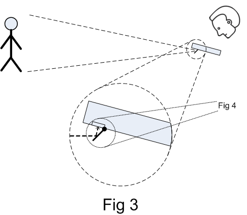
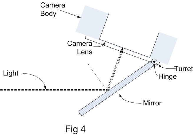
Figure 3 and Figure 4 depict more detailed views of the reflecting mirror. Click on the figures to enlarge them. Figure 4 shows the hinge that allows the mirror tilt angle to be adjusted.
The camera can be operated in landscape mode rotating the by tilt axis of the mirror by 90 degrees. This also allows recording of scenes to the right or left. An ideal implementation would allow the mirror to be rotated 360 degrees along the view axis. The mirror assembly could be mounted on a turret that can be manually rotated, possibly using a thumb wheel. The turret would be shaped like a washer and would be mounted on the camera body so that it could rotate. The mirror hinge would be mounted on the turret. The turret can optionally have indents at 15-degree intervals to provide default rotational positions.
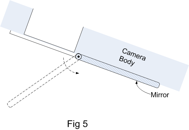
The mirror should be completely retractable to allow recording in the original mode. It should be minimally obstructive while retracted, ideally stowed flat along the camera body. There are several designs to meet this requirement. The hinge can allow the mirror to flip back completely, as shown in Figure 5. The downside here is that the reflecting surface of the mirror will be left exposed and unprotected.
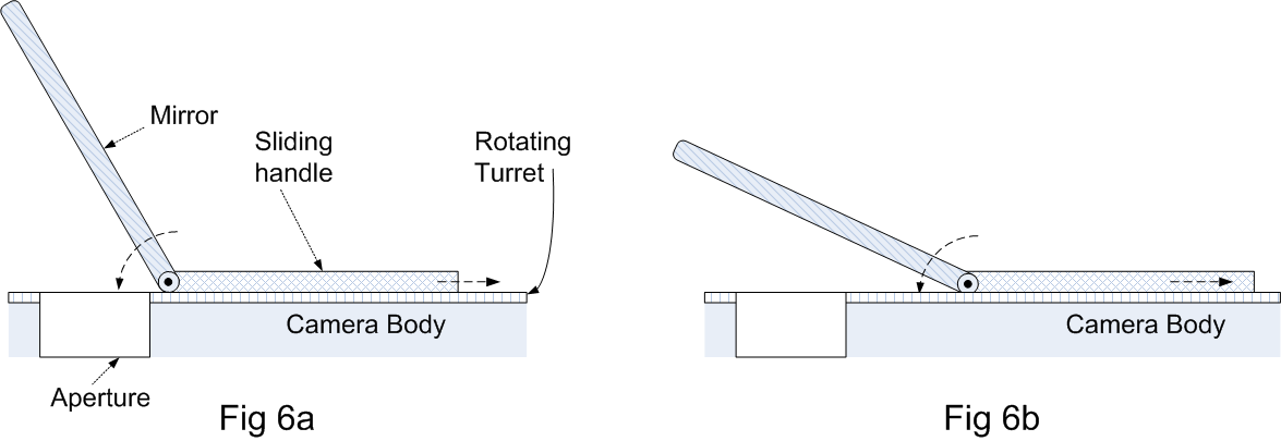
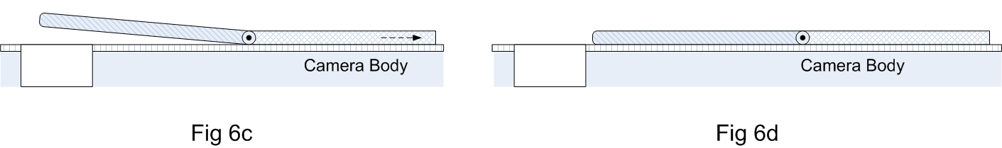
A better design would have the mirror slide out of the way of the camera. The tilt angle would reduce to zero as the mirror is pulled away, thus allowing for tilt adjustment. Figure 6ab and Figure 6cd show a rough depiction of such a design. Figure 6a shows the mirror in the recording position. Figure 6b shows the mirror starting to fold as it is being retracted by its sliding handle. Figure 6d shows the mirror folded and retracted. The sliding parts are mounted on the rotating turret.
Prisms
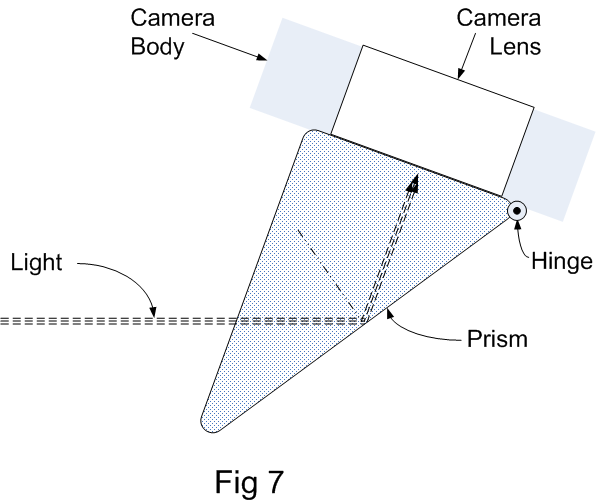
Figure 7 depicts a simple implementation that uses a prism mounted on the mobile phone case. One face of the prism is flush with the camera lens while the other points in the forward direction. Light from the front will be internally reflected by the angled face. The prism could be a right triangular prism with one right angle, and the other two angles could be around 45 degrees. Note that if the angles are 45 degrees, then the mobile phone would have to be held horizontally to record the scene ahead, which would be an inconvenient position. The dashed line indicates the path of the incoming light. The mobile phone is depicted as being held at an angle that allows the display to be viewed conveniently. The prism depicted below has a 60° angle and allows for conveniently recording the scene ahead. A major problem with prisms is that the reflection angle cannot be adjusted by the photographer.
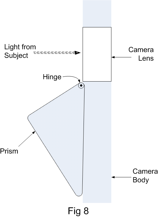
The prism depicted in Figure 7 could be moved out of the camera’s field of vision by swinging it around a hinge. Figure 8 depicts the stowed position. Another problem with this implementation is that the prism cannot be completely removed and will always protrude from the case. Though prisms are sturdier, mirrors seem to be functionally preferable. Besides allowing the tilt angle to be adjustable, the mirror can be cleanly stowed away when it is not needed. The optical quality of a mirror would be better than that of a prism.
Software
The image recorded image will be inverted along the axis parallel to the hinge. If the prism is pointing straight ahead, then the image will be inverted top to bottom, or along the horizontal axis. A software app running on the mobile phone can restore the data to display the correct scene. If the reflecting device is rotated to capture an image sideways, then the image must be flipped left to right, or along the vertical axis.
In general, the image must be flipped along the axis parallel to the hinge of the prism or mirror. If the mirror is part of the mobile phone case, the software may not have a way to sense the axis of the hinge. The user will have to provide that information to the software. The software could use heuristics or AI to optically determine the horizontal plane and automatically rotate the view.
Problems
Field of View
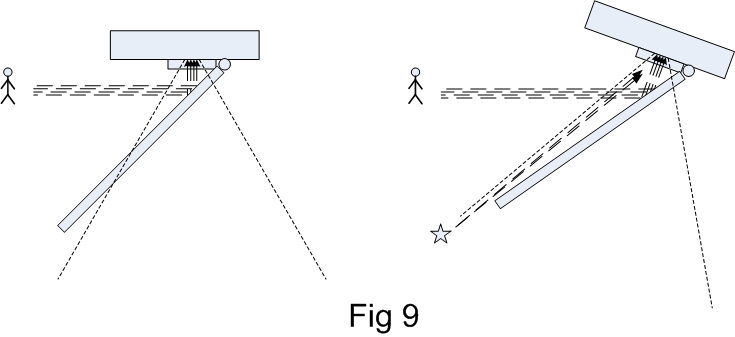
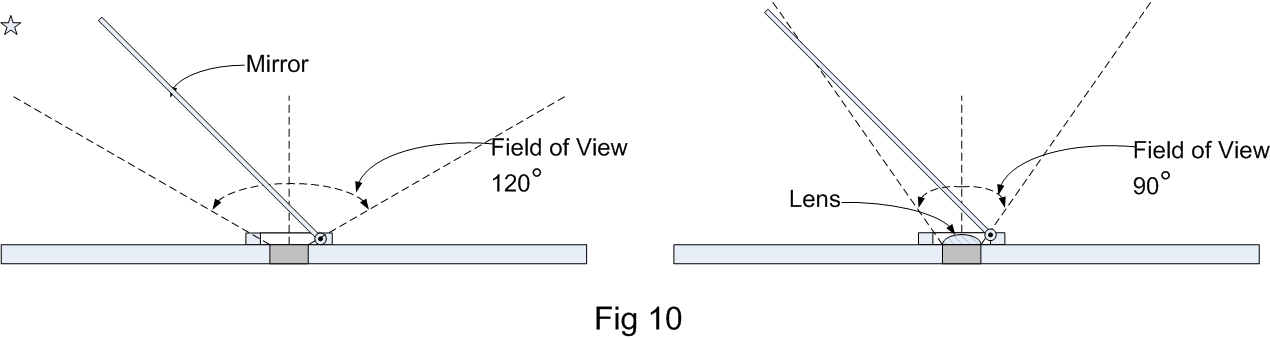
The reflecting surface will need to be large compared to the camera lens. The field of view is a cone with a vertex angle that may exceed 120 degrees for wide-angle cameras. As depicted in Figure 7, a mirror needed to cover the field of view at high tilt angles would have to be very large. An inadequate mirror length is illustrated in Figure 9 (right) and Figure 10 (left.) Undesired light from the star shaped object would be captured in the photograph. Ideally, only reflected light should enter the camera. A solution could be to place a convex lens close to the camera to reduce the camera’s angle of view, as shown in Figure 10 (right.)
Camera Accessories
Most cameras feature flash devices that point in a fixed direction. The effect of the flash may be reduced if the field of vision has been redirected. One solution would be to include a auxiliary mirror parallel to the reflecting surface to redirect the flash and illuminate the subject.
Modern cameras are equipped additional sensors like a flicker sensors, and laser or ultrasonic range finders. These sensors are typically pointed in a static direction and may be adversely affected.
Social Impact
With traditional cameras, it is evident when a subject is being photographed. This proposal may make the act of recording less obvious and could infuriate some individuals who feel that they are being recorded surreptitiously. A photographer can even be facing away from the subject. This is not illegal. According to the US First Amendment, individuals should have no expectations of privacy regarding photography in public places. However, given the negative experience of Google Glass, public sentiment may be a powerful force that can hinder the acceptance of this product.
Optional
Enhancements
A convex mirror may be utilized to increase the field of view, producing effects similar to those of a fisheye lens.
The mirror could be tinted or polarized.
A parallel mirror in front of the flash could redirect the illumination to the subject.
A design could be developed for the forward camera as well.
Prior Art
This is a straightforward idea with a low-cost method of implementation. However, it has not been popularized or commercialized by anyone as yet. A quick search found no comparable patent assignments.
The following devices can be considered for comparison:
1. A periscope allows for viewing over an obstacle. It always comprises of two reflecting surfaces that may be adjustable.
2. An endoscope permits directional view adjustments but employs flexible fiber optic cables and no mirrors.
3. Belay glasses are utilized by rock climbers to view the scene above them without excessively tilting their heads upward.
None of the above devices are associated with cameras. A provisional patent has been filed for this concept. It covers video and still photographs on mobile phones and other cameras. An international patent should be considered, since a majority of sales will be in China and India, despite the fact that patent protections are weak there.
Prototypes

A few ‘proof of concept’ prototypes have been built using a 3D printer. The picture above shows a 45 degree prism mounted to take landscape mode pictures when the mobile phone is held horizontally. The green plastic case clamps on to a mobile phone. The concept worked, but the image was cloudy. Perhaps the optical quality of the $10 prism was not good enough.
The animated figure above depicts how a mirrored surface can be constructed. It will be flat when it is not in use and the angle can be adjusted as needed.
An open source camera application for Android has been modified to invert pictures. Users will have to use this app instead of the stock camera app while utilizing the mirror function. The app can allow the user to invert the image along arbitrary axes, following the rotational setting of the mirror.
Next Steps
A prototype
has been demonstrated to several potential customers in the USA. The reaction was generally positive. The younger generation thought it was cool,
the older folk appreciated the convenience, while the middle aged audience was
worried about the perceived invasion of privacy. A similar test should be performed in other
countries, especially in China and India.
A
range of designs will be developed, for example, the tilt axis could be fixed
or could allow for rotation. Rotation
could be limited to 90°, 180° or allow a full 360°. The mirror may be
stowed by flipping it over or sliding it out of the way. The quality of the mirror and lens could be
varied, giving customers price vs. quality options.
A
patent application has been filed in the USA, but additional international filings
may be justified for China and India.
Strategy
A
business plan will be developed that describes the commercialization strategy,
potential costs and profits, resource and manpower requirements. The primary strategy will be to integrate
this concept into mobile phone cases. Phone
cases are customized for each model of phone and there are many manufacturers
for cases. These manufacturers will be
contacted. It will help them to
differentiate their products from their competition. A CAD design will be offered to help them to easily
incorporate this concept into their case designs. Given that the retail price of cases is only
between $10 and $50, the revenue per individual case sale will be low and
monitoring sales volume will be challenging.
Vendors could be offered a license for unlimited production.
© 2025, Cue Group, Patent
pending